


Check back soon
Once posts are published, you’ll see them here.


![[Embedded Low Power] Temperature Display](https://img.youtube.com/vi/rQbG31gI3uw/mqdefault.jpg)


Project Details
Title: Light Programmable Robot
Class: Electronics Design Laboratory
Semester: Spring 2018
Team: Sonya Schuppan, Kenneth McCarthy, Jiabin Lin
Software: Arduino
Hardware: Arduino UNO, circuit for the Robot
Given Hardware: Robot platform, DC Motors with an optical encoder for sensing rotational frequency and direction
Programming language: Arduino
Simulation tool: LTspices, Oscilloscope
Introduction
The purpose of our project is to create a robot that can receive and react base on the data transmitted to it by sensing the high intensity of light pulse from the flashlight. We accomplished it by building a feedback circuit that is able to control the robot's speed by detecting the pulses sent from the Arduino. Arduino takes the input from the flashlight, and output different pulses to control the entire robot. We design sixteen actions that the robot can be programmed including two commands "start programming" and "end programming" and fourteen "programmable action".
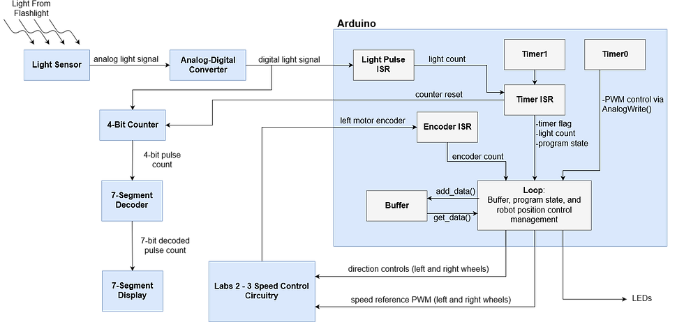
Figure 1: Top level block diagram of the Light Programmable Robot
Hardware
We are provided a robot platform with two DC Motors with optical encoders for sensing rotational frequency and directions as shown in Figure 2. The voltage supplies of the motor can safely vary from -10 V to 10 V and the power supplies of the encoder should be kept between 7 V to 10 V to prevent damage to the encoder while it still can work properly.
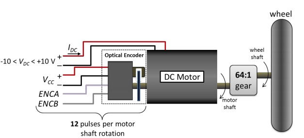
Figure 2: DC motor with the encoder and wheel
Measuring the speed of the wheel by measuring the encoder frequency is not very practical. However, it is much easier to measure a DC voltage that is linearly related to the encoder frequency. We created an LTspice model of the circuit described in lecture whose purpose is to output a DC voltage that is linearly related to the speed of the rotation of the wheel. The idea of this circuit is to convert the pulses from the encoder to square pulses through the 555 timer circuit, then the "average" circuit converts the square pulses to the average DC voltage. We choose C2 as 10µF and R2 as 5k Ω based on the equation t(on) = R2*C2*ln(3) and t(on) is around 90% of the minimum encoder period. In order to get a good average of the PWM we needed to make the product of R3*C3 to be 50ms. This time constant allowed the circuit to have an acceptable response time, while also being much larger than the lowest PWM period. To do this we chose R3= 5kΩ and C3=10 µF.
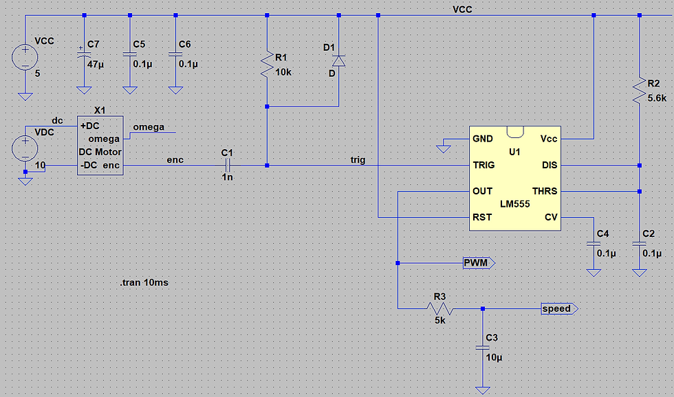
Figure 3: Speed sensor circuit including motor model, trigger circuit, 555 timer one-shot circuit, and averaging circuit
Next, we need to build a motor driver circuit, which will allow the wheel to spin in both clockwise and counterclockwise directions. Building the motor driver circuit will involve 2 npn and 2 pnp transistors that will be connected to heat sinks in order to protect the components from overheating. The design of the motor driver circuit was shown below in Figure 4.
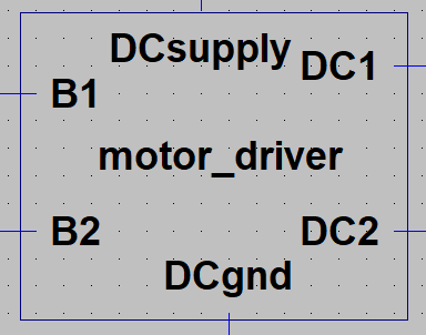
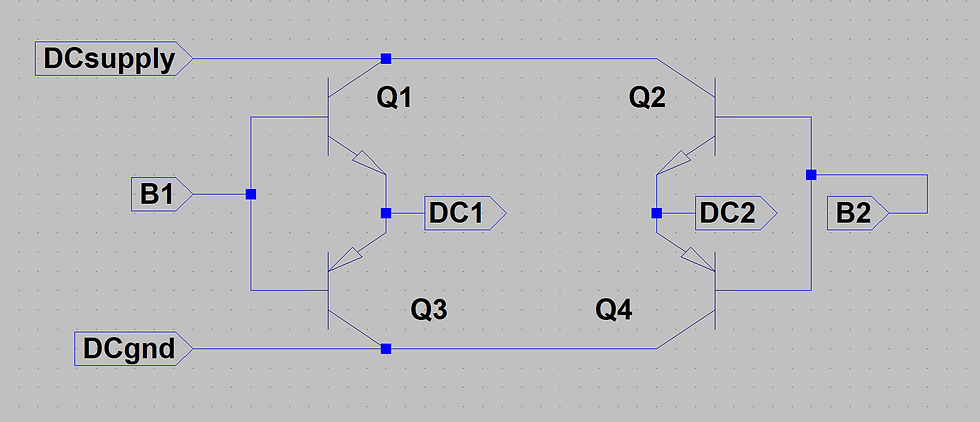
Figure 4: Motor driver transistor circuit and corresponding symbol created in LTspice

Figure 5: Full motor driver circuit with Rb values calculated from the ideal model, with the voltage drop across the transistor diodes assumed to be 0.8V
We then need to build a feedback circuit that will allow us to control the speed of the wheels with a PWM reference voltage from an Arduino. The feedback circuit itself is shown in Figure 6. The feedback circuit included an integral compensator to adjust the voltage from the sensor circuit and a PMOS transistor to activate the output. We used two of these feedback circuits, one to activate clockwise direction of the wheel, and one to activate counterclockwise direction of the wheel. We designed the complete speed control circuit in LTspice, which is pictured in Figure 7. This schematic includes blocks for the motor, motor driver, speed sensor, and the clockwise and counterclockwise feedback circuits.and a PMOS.
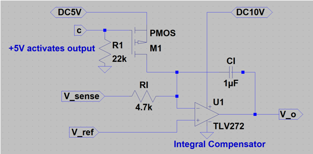
Figure 6: Feedback circuit including an integral compensator that adjusts V_sense, and a PMOS transistor to activate or deactivate the circuit
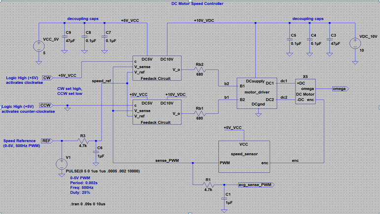
Figure 7: Complete motor speed sensor circuit. Current setup includes a reference PWM (REF) from 0-5V with a duty cycle of 25% and a frequency of 500Hz. The clockwise direction is activated by connecting it to +5V and the counterclockwise direction is deactivated by connecting it to ground.
In order to build the Light sensor, we chose the photoresistor to sense the light. When light is incident on the photoresistor, the resistor decrease.We create a voltage divider as shown in Figure 2. Our goal is to have the output voltage be below 2.5V when the flashlight shines on the photoresistor and above 2.5 V at all the other times. In our case, when light shines on the photoresistor, the resistor of photoresistor is about 1k Ω, and the resistor in room light is about 3.3 k Ω. In order to reach our goal, we choose 1.5 kΩ as the non-photo resistor.
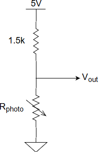
Figure 6: Schematic of the analog light sensor.
The analog-digital converter takes the output of the light sensor as the input. This analog to digital converter circuit output 5V whenever the voltage is below 2.5 V and 0 V when it is greater 2.5 V. This acts as a digital signal that tells if the flashlight is incident on the photoresistor or not, as normal room lights would not be bright enough to send the digital signal high. The design of the analog-digital converter is based on a single voltage comparator made with an op-amp. A basic voltage divider of two 100 kΩ resistors converts the 5 V power to a 2.5 V reference voltage that is put into the non-inverting input of the op-amp. The output of the light sensor (Vin) is then put into the inverting input. A 560kΩ was added in order to add a small amount of hysteresis to the comparator. This fixes the noise pulses from the photoresistor.
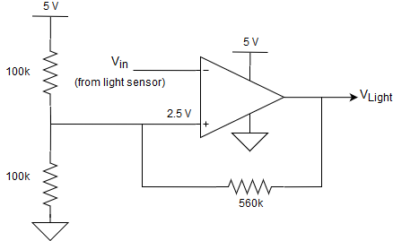
Figure 7: Schematic of the analog to digital converter circuit.
The output of the digital light was taken to SN74HC161N 4-bit counter chip and Arduino. The output voltage from the analog-digital converter was connected with the clock pin in the 4-bit counter. At every positive clock edge, the 4-bit counter will increment by one in binary. We sent this 4 bit binary to the decoder and use seven-segment to display the number of the light pulses.

Figure 8: Block diagram of how components of counter circuit are connected to each other and to other components of robot. VLight is the same signal as in Figure 7.
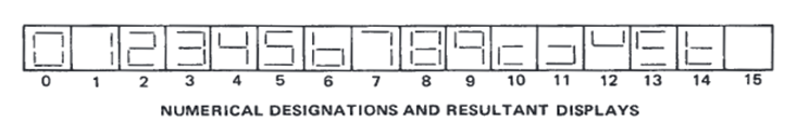
Figure 9: How the 7-segment decoder displays numbers 1-15. Not standard hexadecimal.
The final additional hardware that was added a series of three LEDs; one yellow, one red, and one blue; that is used in one of the operational modes of the robot. Three of the programmable commands is to make one of these three LEDs blink three times. The power for the LEDs thus comes from a digital 5V signal from the Arduino.

Figure 10: Schematic showing how LEDs connect to Arduino and ground.
Software
The role of the software in this project is to manage the timing and operation for both the transmission of data and the position control of the robot. This is done by managing a FIFO circular buffer that stores a series of programmable actions and managing the flow between program states. For this application, we refer to “commands” as data sent to the robot that tells it to change or maintain state. In this case, we have only two commands: “start programming” and “end programming.” We refer to “programmable actions” as the data sent to the robot that tells it how to move. These are encoded in the integers 3 to 15. To store the data, we create a C++ library for a FIFO circular buffer that is able to add data and get data. This buffer is meant to store the light pulse counts that are input to the Arduino from our light-sensing circuit. We accomplished this by using a dynamically allocated array. The rest of the code for our project is essentially built around this buffer in order to manage the flow of data in and out of it.
Counting the number of light pulses that the user enters was done by connecting an interrupt pin on the Arduino to the digital light pulse signal created by our comparator circuit. We used a global variable to keep track of the number of rising edges seen. Since the count must be reset every 10 seconds, we used Timer1 to manage the timing and resets.
To manage the timing in our program, we configured an interrupt on Timer1 of the ATmega microcontroller so that it would set a flag to 1 in the main loop every 10 seconds. Since this timer flag indicates that a new command is ready to be processed, if this flag is set to a 1 in the main loop, the program will enter a “process command” state. In addition to setting the timer flag, we also used the Timer1 ISR to save the current count immediately after the interrupt occurs and manage the program state. Saving the current count to a new variable allows for the count to reset immediately and wait for the next command, even if the previous count has not yet been added to the buffer. The program state is used to switch between collecting data inside the buffer and reading/acting upon data inside the buffer. Lastly, we also used the timer ISR to manage the output of one of the Arduino pins to control the reset of our external counter chip.
In the “process command” state of the main loop, data is either added to the buffer (when the program state is equal to 1) or a “do it” flag is set (when the program state is equal to 2). This state also contains checks to ensure that the data is valid (i.e between 3 and 15) and that the buffer is not full. If the buffer is full, the robot will enter the “do it” state without requiring an “end programming” command to be sent from the user.
When the “do it” flag is set, the program will enter a loop that contains a case statement. This case statement reads off the elements in the buffer one at a time and calls the position control functions associated with the data read from the buffer.
Challenge
challenge we are still not able to resolve and remain in our final project. The seven-segment skip 2 and 8 when the counter circuit start counting, even if we input the correct square wave. There are other small glitches in the final design, but they are resolved quickly. These glitches included us not realizing low battery caused our encoder stop working, bad soldering in one of the motor driver caused one of the wheels to stop working, and drawing too much power with our 7-segment display due to not having current limiting resistors. These were fixed by replacing batteries, re-soldering the motor driver circuit and adding resistors to the 7-segment display.For software, when we were adding our position control code to the buffer and timer code, the Arduino generates 100% duty cycle PWM which makes the robot only moves in full speed. After much searching on the internet to find the definition of AnalogWrite() , we found that this function is using the same timer to generate PWM as we were using the 10s intervals. This makes sense, because we kept overwriting the use of this timer. From the AnalogWrite() function definition, we saw that the timer used in it was dependent on the pins. We changed the pins of the reference PWM outputs in our code so that they would be using a different timer, and once this was done, everything worked perfectly.There are many challenges in the final design. We connect the digital light to the 4-bit counter, it increments more than once when we shine the light to the photoresistor (noise). The noise is so subtle that we did not notice in the oscilloscope. After debugging this problem for a long time, we finally realised that the noise is the problem. This was fixed by introducing hysteresis to the comparator through a large 560 kΩ resistor which made it so there was a threshold band between ~2.3V and ~2.7V above which the output would be low and below which the output would be high. The second
Video
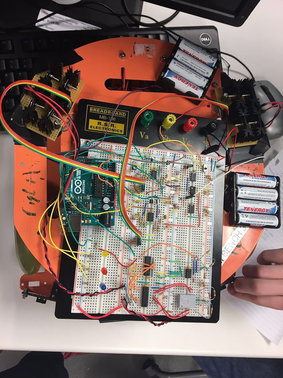
The Circuitry of the light programable robot
Comments